For this assignment, our class was tasked with creating a device that could connect to a server via a TCP network socket in order to play a “ball drop game”. Our device needed to be able to indicate when it was connected to the server, to move a platform character within the game, and to connect to the server with a button press. After registering my Arduino nano’s MAC address with NYU’s Wifi Network, I started building the hardware for my device with a simple four-button layout, to ensure that I could transmit the messages necessary to interact with the game platform/character.
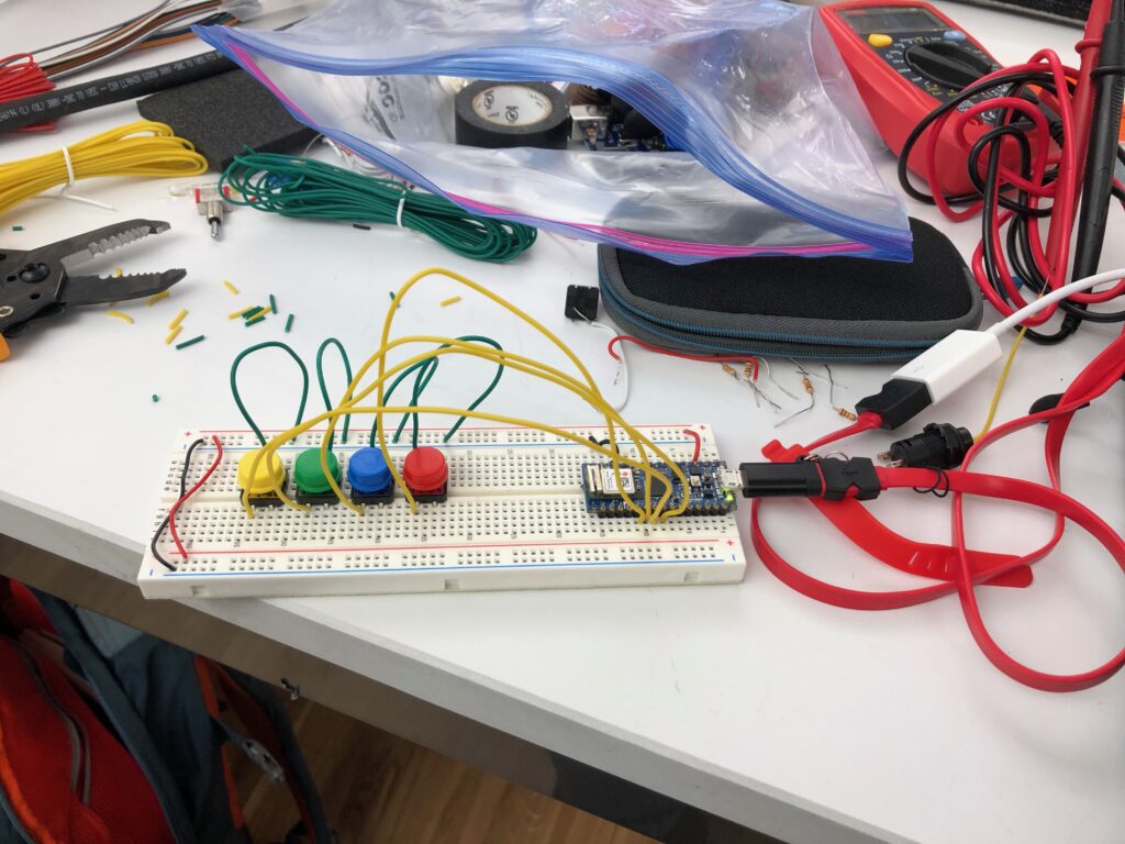
I struggled most with troubleshooting this step – I discovered that the breadboard I had been working with was partially broken and that my Arduino was broken and could not use its built-in wifi capabilities. I ended up using a new smaller breadboard, a new Arduino nano and connected my directional buttons via a PCB board.
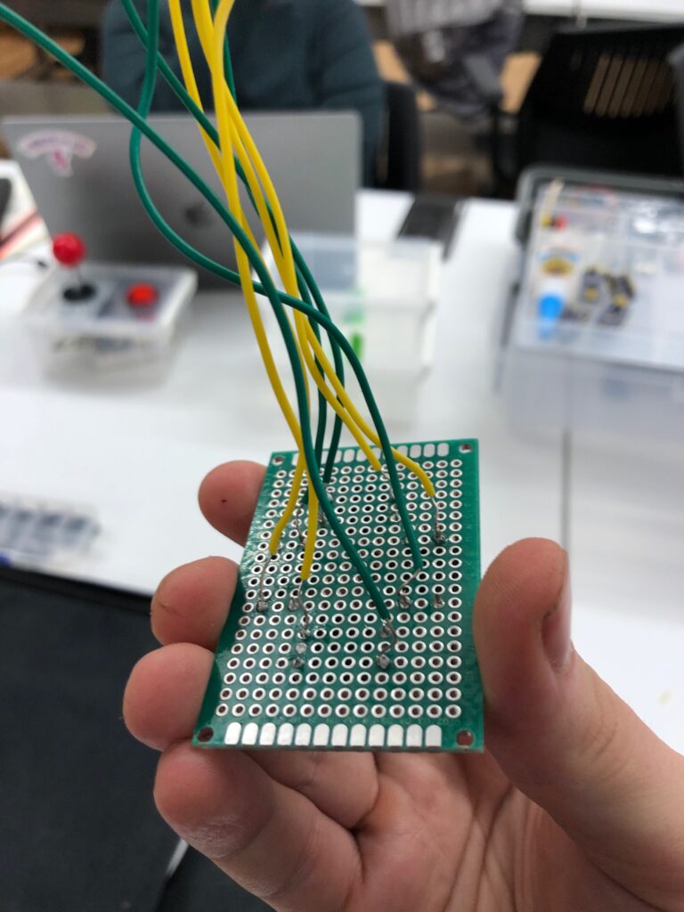
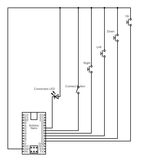
From there, I adapted an example code provided by Tom Igoe to use a push-button with a built-in LED to fulfill my network connection button, and network connection indicator requirement. This code also required me to integrate my 4 button controls (instead of Tom’s joystick code) and the WIFININA Arduino library to Arduino Nanos (the original code was intended for a different type of Arduino). Once my circuit and code were sufficiently debugged, I was able to play the ball drop game, and I moved on to fabrication. I tried two iterations of my controller enclosure with two kinds of cardboard.
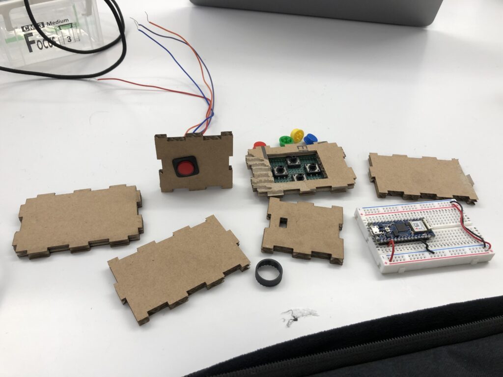
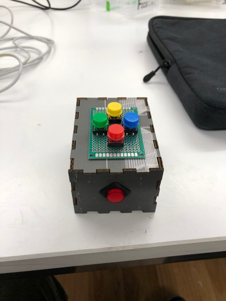
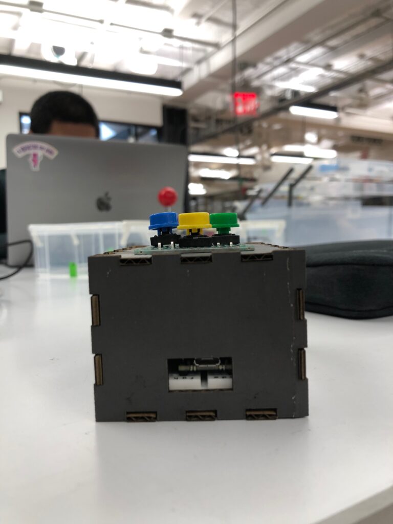
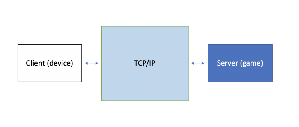
My final circuit diagram, system diagram, and final product images can be found below:
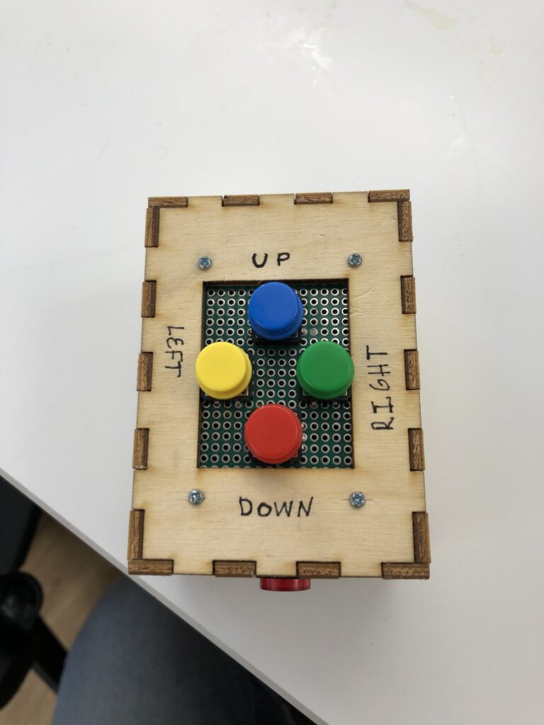
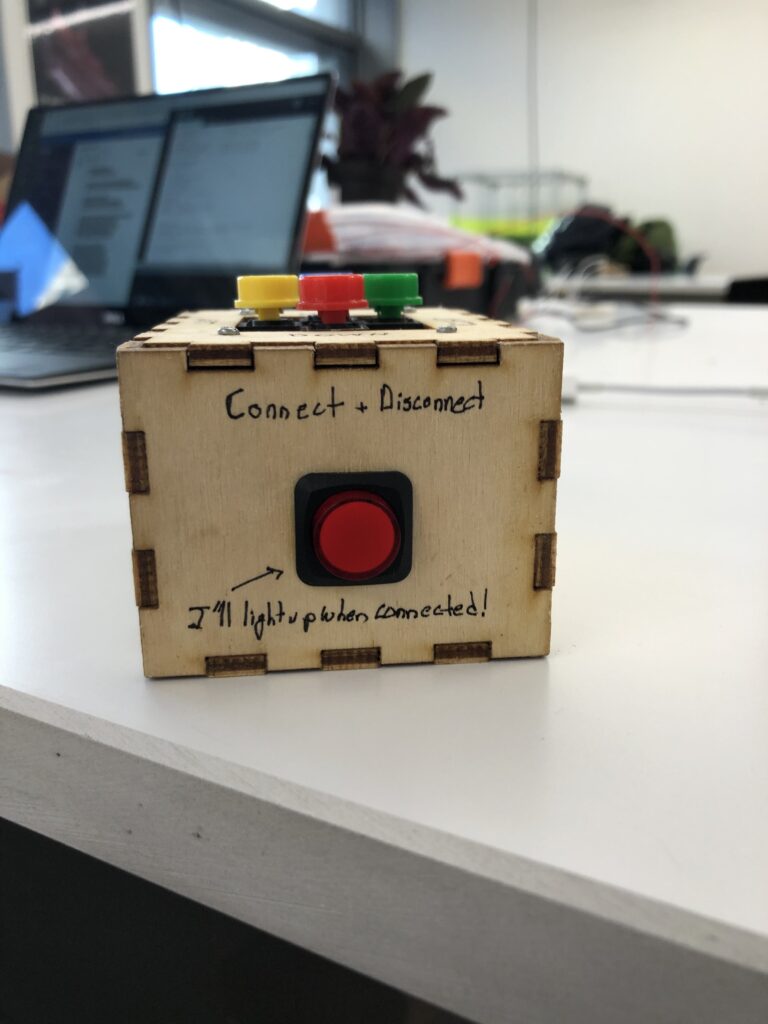
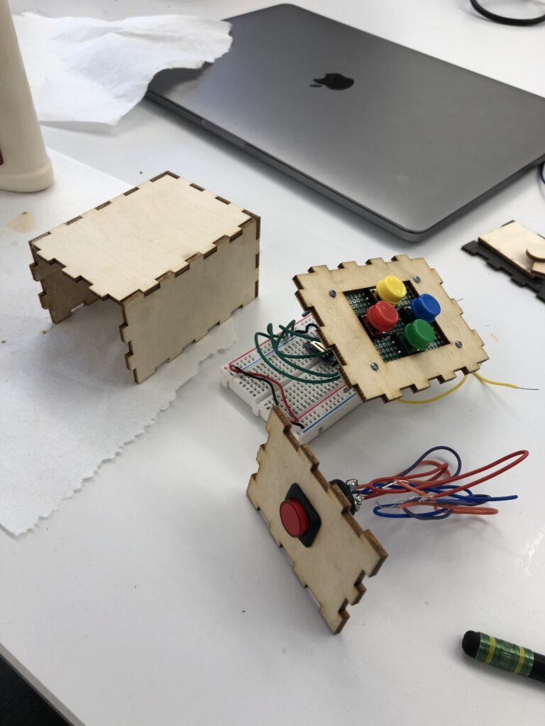
Below is a video of my controller in action:
I have linked my code in a GitHub repository, note that for security purposes I have not included the file with my network name and password, and the IP address written into the code will vary.